
Top Fibre Optic Ducting Types for Underground Installation
Underground fibre networks depend on more than the cable inside them. The duct must withstand burial conditions and leave room for future work. A crushed conduit beneath a busy road can turn a routine cable replacement into an expensive excavation. Access matters. Choosing fibre optic ducting means weighing ground conditions, installation methods, cable dimensions, and the likelihood of future network expansion. This guide examines common options, including HDPE ducts, PVC conduits, and microduct systems, with attention to their practical strengths and limitations.
HDPE ducting offers flexibility and is commonly supplied in long coils, reducing the number of underground joints. Rigid PVC conduit can suit planned routes where straight sections and compatible fittings make installation manageable. Microduct systems provide smaller pathways for compact fibre cables, often installed using compressed air. Size matters too. The right internal diameter depends on cable size, route length, bends, and the proposed installation method. For air-blown installations, duct cleanliness, joint integrity, and equipment compatibility also affect how far a cable can travel.
There is no universally best option, and choosing the toughest-looking duct can still produce a poor result. A flexible product may simplify routing, yet inadequate bedding or unsuitable backfill can undermine its performance after burial. Equally, reserving extra capacity sounds sensible, but unused pathways still need sealing and clear identification. These details are easy to underestimate. Comparing duct types against manufacturer specifications and project requirements helps turn a product choice into a maintainable underground installation.
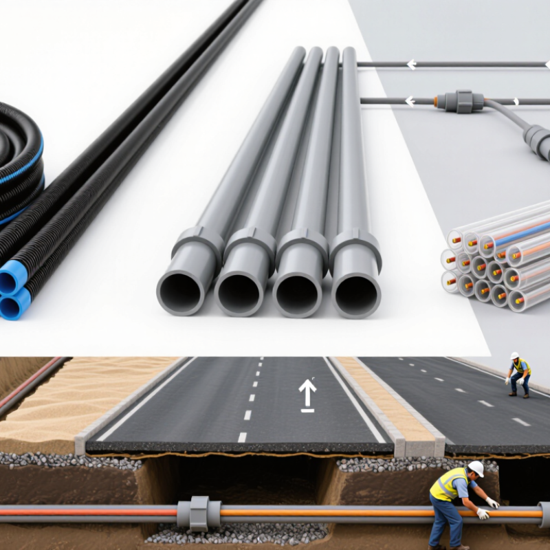
HDPE Ducts: Flexible Protection for Underground Fibre Optic Cables
HDPE ducts provide flexible protection for underground fibre optic cables, especially along routes with gradual bends and uneven ground. Their smooth inner walls help reduce friction during cable pulling or air-assisted installation. Flexibility has limits. Tight bends can still restrict installation and make future cable replacement difficult. On a typical street route, long duct sections can reduce buried joints between access chambers. Fewer joints mean fewer potential entry points for silt and groundwater, provided connections are properly sealed.
Choosing a duct involves more than matching its diameter to the cable. Installers also consider burial depth, ground conditions, traffic loads, and the intended installation method. Wall thickness matters. A duct beneath a vehicle crossing may require different protection from one installed along a landscaped verge. HDPE resists many substances found in soil, but crushed stone or poor bedding can still damage it. Suitable bedding and controlled backfilling help prevent concentrated pressure against the duct wall.
Installation details often determine whether that protection lasts. Cap open ends during storage and installation to keep mud and small stones outside. Before cable installation, check duct continuity, clear obstructions, and confirm that bends meet the specified radius. A route that looks tidy above ground can still hide a flattened section below. It is tempting to skip these checks when schedules tighten, but locating damage after reinstatement is considerably harder.
| HDPE Duct Type | Construction | Main Advantages | Typical Underground Applications | Cable Installation Method | Key Selection Considerations |
|---|---|---|---|---|---|
| Smooth-Wall HDPE Duct | Solid HDPE wall with smooth internal and external surfaces; available in continuous coils or straight lengths. | Flexibility accommodates route changes. Continuous lengths can reduce the number of joints. HDPE resists corrosion. | Trenched telecommunications routes, appropriately specified trenchless crossings, and subduct installations within larger conduits. | Cable pulling; air-assisted installation where the duct, cable, joints, and equipment are suitable. | Select wall thickness, diameter, and mechanical rating for burial conditions and installation loads. Check cable clearance and minimum bend radius. |
| Internally Ribbed HDPE Duct | HDPE duct with ribs formed along the internal surface, commonly with a smooth exterior. | Internal ribs can reduce cable contact area and influence friction during installation; performance depends on the rib profile and cable. | Underground cable routes where installation friction is an important design consideration. | Cable pulling or air-assisted installation, depending on the specified duct system. | Use the effective internal clearance when sizing the duct. Confirm rib geometry, cable compatibility, lubrication requirements, and pressure suitability. |
| Low-Friction Lined HDPE Duct | HDPE duct incorporating an internal low-friction layer, such as a co-extruded silicone-based lining. | Designed to reduce friction between the cable sheath and duct wall, helping manage installation forces. | Routes with demanding cable installation lengths or bends, subject to installation calculations. | Cable pulling and, for suitably rated systems, air-assisted installation. | A low-friction lining does not guarantee a particular installation distance. Check cable sheath compatibility, route geometry, allowable pulling tension, and lubricant guidance. |
| Dual-Wall Corrugated HDPE Duct | Corrugated external wall with a smooth internal bore. | The external profile provides structural stiffness while the smooth bore supports cable passage. | Buried cable protection in trenches, including road and utility corridors where the selected product meets project requirements. | Usually cable pulling through an installed duct route with suitable access points. | Check ring stiffness, burial depth, traffic loading, bedding, and joint performance. Air-assisted cable installation requires a system specifically rated for the operating pressure. |
| Individual HDPE Microduct | Small-bore HDPE tube designed for compatible optical microcables or blown fibre units. | Supports incremental fibre deployment and makes efficient use of available pathway space. | Access networks, fibre-to-the-premises distribution, and subdivision of larger existing ducts. | Air-assisted installation using compatible microcables or fibre units and installation equipment. | Match the microduct bore to the cable or fibre unit. Direct burial requires a suitable microduct specification; thin-wall products may require an enclosing duct. |
| Sheathed HDPE Microduct Bundle | Multiple HDPE microducts grouped within a common protective sheath, typically with individually identifiable tubes. | Provides separate pathways for staged network expansion and simplifies identification of individual routes. | Distribution networks and feeder routes requiring multiple independently usable microduct pathways. | The bundle is installed first; compatible cables or fibre units are subsequently blown into individual microducts. | Choose a bundle rated for direct burial or installation inside a larger duct, as appropriate. Check crush resistance, bend radius, branch connections, and sealing requirements. |
Material: HDPE means high-density polyethylene. It provides a corrosion-resistant cable pathway, but resistance to crushing, deformation, and installation loads depends on the duct design and installation conditions.
Design note: These categories can overlap: a microduct may also have internal ribs or a low-friction lining. Final selection should follow the applicable telecommunications conduit specification and the product’s verified mechanical and pressure ratings.
Installation note: Burial depth, bedding, bend radius, cable fill, pulling tension, and blowing pressure must be determined for the actual route and cable system. Buried ducts can accumulate water; use cables suitable for the expected environment and seal duct entries appropriately.
Related Posts
-
China Top 10 Fibre Optic Ducting Manufacturers?
-
What Is the Best Ducting for Cables in 2026?
-

What is Fibre Drop Cable and Its Uses in Network Installation
-

How to Choose the Right Fibre Cable Duct for Your Project?
-
China Top 10 Fibre Cable Installation Companies?
-
China Top 10 FO Cable Manufacturers for Global Buyers?