Top 10 Fibre Optic Network Cable Types for Buyers

Choosing the right fibre optic network cable is rarely a simple matter of selecting the highest bandwidth.

Real installations involve distance, connector density, bending space, weather, fire risk, and maintenance access. A data-centre link may need OM4 or OM5 multimode cable, while a metropolitan route usually demands OS2 single-mode performance. FTTH projects often require compact drop cable designs. Industrial sites may need armoured or bend-insensitive construction.

Dr. Charles K. Kao, widely recognized as the father of fibre-optic communications, said, “The use of optical fibre for communications is the most important application of optical fibre.” His vision still influences network planning today. Fibre is not merely a replacement for copper. It changes how engineers manage capacity, distance, and future expansion.

This guide examines ten practical fibre optic network cable types for buyers. Each option has strengths, limits, and installation conditions that deserve careful attention. Some cables perform brilliantly in controlled indoor environments but become poor choices outdoors. Others cost more initially yet reduce repair work later.

There is no universal winner.

Buyers should compare fibre mode, core size, jacket material, bend radius, connector format, attenuation, and applicable testing requirements. Verified insertion-loss results matter more than attractive product language. Standards and manufacturer data should be checked before purchase. That step is often skipped.

The following cable types are evaluated from a practical purchasing perspective. The aim is not to promote the most expensive solution. It is to match the cable with the network’s actual route, workload, environment, and expected growth.
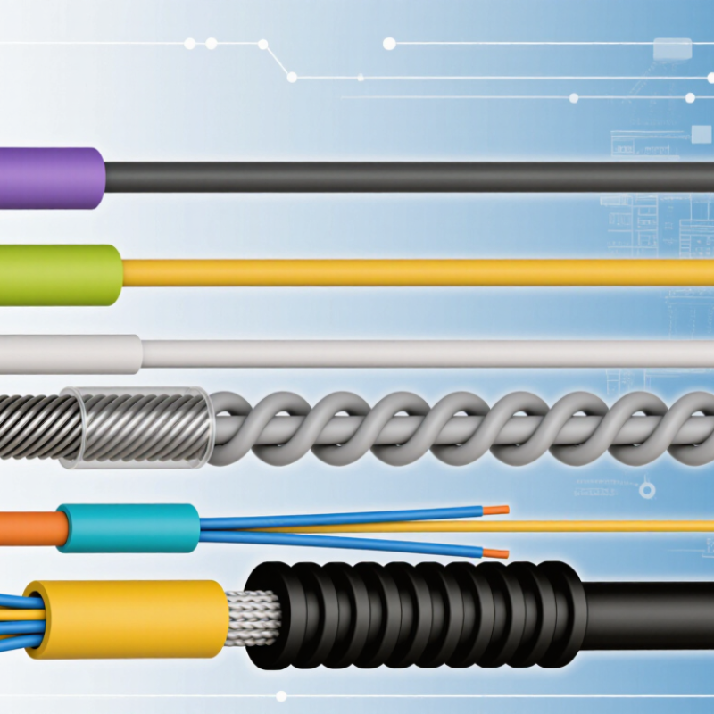
Top 10 Fibre Optic Network Cable Types for Buyers

Classify the 10 Fibre Cable Types by Mode, Core Size, and Standards

Fibre cable selection begins with mode. Singlemode carries light through a roughly 9-micron core, while multimode uses larger 50- or 62.5-micron cores.

Cisco’s Annual Internet Report forecast 5.3 billion internet users by 2023, increasing pressure on scalable infrastructure. Distance still decides the design.

The ten buyer-facing types are OS1 and OS2 singlemode cables, plus G.652.D, G.657.A1, and G.657.A2 designs.

OS1 suits indoor structured cabling, while OS2 supports longer outdoor and campus links. G.652.D is the common low-water-peak fibre. G.657.A1 and A2 tolerate tighter bends.

The multimode group includes OM1, OM2, OM3, OM4, and OM5. OM1 uses a 62.5-micron core; the other four generally use 50-micron cores. OM3 and OM4 commonly support 10 Gigabit Ethernet to 300 and 400 metres, respectively, under IEEE and TIA application guidance. OM5 can assist short-wavelength-division multiplexing, but equipment compatibility needs checking.

Standards prevent costly assumptions.

ISO/IEC 11801 and TIA-568.3-E define performance and cabling practices, while ITU-T G.652 and G.657 describe singlemode characteristics. Actual reach depends on transceiver power, connector loss, polarity, and installation quality.

A 2024 optical-networking market outlook from LightCounting also links rising data-centre bandwidth with continued demand for higher-speed optical components. The categories overlap, imperfectly.

Buyers should verify the exact core, attenuation, jacket rating, and test results before ordering. The cheapest cable may create the longest troubleshooting session.

Compare OS1 and OS2 9/125 µm Fibre for 10GbE Links up to 40 km

For 10GbE links, OS1 and OS2 fibre both use a 9/125 µm core and cladding design. The similarity can mislead buyers during installation. OS1 is commonly built for controlled indoor environments, using tighter buffering and typical attenuation near 1.0 dB/km. It can support 10GbE across shorter routes when the transceiver and loss budget are suitable.

OS2 is usually the safer choice for outdoor cabling and links approaching 40 km. Its typical attenuation is about 0.4 dB/km, leaving more power margin for connectors, splices, patch panels, and ageing. The fibre alone does not create a 40 km connection. A compatible 10GbE optical module, usually operating near 1550 nm, must support that distance. Dispersion and receiver sensitivity also need checking.

Measure the installed route, rather than trusting the cable label. A 36 km path may become 39 km after risers, service loops, and equipment-room routing. Clean every connector before testing. Small contamination can consume valuable loss budget. In field commissioning, technicians often discover that poor splices matter more than the OS1-versus-OS2 decision. OS1 may appear cheaper for a short indoor link, but migration plans can change. I would specify OS2 when future distance, outdoor exposure, or network expansion remains uncertain. Still, this is not universal; the optical budget and local cable construction should decide.

Top 10 Fibre Optic Network Cable Types for Buyers - Compare OS1 and OS2 9/125 µm Fibre for 10GbE Links up to 40 km

Reach values are typical IEEE Ethernet application distances and depend on transceiver class, connector loss, splice loss, link budget, installation quality and compliance with the applicable cabling standard.
No. Cable type Core / cladding Typical construction Common wavelength(s) Typical 10GbE application and reach Typical attenuation / performance note Best suited for Buyer considerations
1 OS1 single-mode fibre 9/125 µm Usually tight-buffered indoor cable 1310 nm and 1550 nm 10GBASE-LR: up to 10 km with suitable optics Designed for controlled indoor cabling environments; verify the cable's specified attenuation and water-peak characteristics. Building backbones, equipment rooms and structured indoor links For new installations, confirm whether OS2 is required for future upgrades or outdoor sections.
2 OS2 low-water-peak single-mode fibre 9/125 µm Loose-tube outdoor or tight-buffered indoor/outdoor cable 1310 nm, 1550 nm and extended bands depending on design 10GBASE-LR: up to 10 km; 10GBASE-ER-class links: up to 40 km with appropriate optics Typically lower attenuation and broader usable wavelength performance than basic OS1 designs; check the datasheet for the exact limit. Campus, metropolitan, outdoor, data-centre interconnect and long-distance links The preferred choice for new long-reach infrastructure; 40 km requires a link budget and 40 km-rated transceivers.
3 OM1 multimode fibre 62.5/125 µm Usually tight-buffered indoor cable 850 nm and 1300 nm 10GBASE-SR: approximately 33 m Older multimode grade with higher modal bandwidth limitations than newer OM grades. Legacy premises networks and short equipment-room connections Not normally selected for new 10GbE installations unless it is already deployed.
4 OM2 multimode fibre 50/125 µm Usually tight-buffered indoor cable 850 nm and 1300 nm 10GBASE-SR: approximately 82 m Improved modal bandwidth over OM1, but shorter 10GbE reach than OM3 and OM4. Legacy office, building and data-centre links Check installed fibre size before purchasing transceivers; OM2 is not interchangeable with 62.5 µm OM1 hardware in every application.
5 OM3 laser-optimised multimode fibre 50/125 µm Tight-buffered or breakout indoor cable 850 nm primarily 10GBASE-SR: up to 300 m Laser-optimised multimode design with higher effective modal bandwidth than OM1 and OM2. Standard data-centre and campus 10GbE links A practical balance of cost and reach for many short- and medium-distance 10GbE runs.
6 OM4 laser-optimised multimode fibre 50/125 µm Tight-buffered or breakout indoor cable 850 nm primarily 10GBASE-SR: up to 400 m Higher modal bandwidth than OM3, supporting longer short-reach Ethernet links. Higher-density data centres and longer in-building backbones Often selected when additional multimode reach is needed without moving to single-mode optics.
7 OM5 wideband multimode fibre 50/125 µm Tight-buffered indoor cable 850–953 nm for shortwave wavelength-division multiplexing 10GbE short-reach links: commonly up to 400 m with compatible optics Designed for multiple shortwave channels; ordinary 850 nm 10G optics do not automatically provide extra reach. Data centres planning SWDM or other multi-wavelength multimode systems Higher cable cost may not provide a benefit for conventional single-wavelength 10GBASE-SR.
8 Simplex single-mode cable Usually 9/125 µm OS1 or OS2 One fibre in one jacket 1310 nm, 1550 nm or application-specific bands Up to 10 km or 40 km according to the selected single-mode optics and link budget Cable geometry rather than fibre grade; one fibre is available for one-way or bidirectional designs. Patch extensions, monitoring, wavelength-division systems and specialised links Confirm whether the application needs one fibre, two fibres or bidirectional operation over a single fibre.
9 Duplex single-mode cable Usually 2 × 9/125 µm OS1 or OS2 Two fibres joined in a zipcord or common jacket 1310 nm, 1550 nm or application-specific bands 10GBASE-LR up to 10 km; up to 40 km with suitable long-reach optics and OS2 infrastructure Two dedicated fibres support conventional transmit and receive paths. Ethernet uplinks, building backbones and data-centre interconnects The common choice for duplex LC-based 10GbE links; maintain polarity and fibre identification.
10 Armoured outdoor single-mode cable Typically 9/125 µm OS2 Loose tube with dielectric or metallic armour 1310 nm and 1550 nm; extended bands by specification 10GBASE-LR up to 10 km; up to 40 km with 40 km-rated optics and a compliant link budget Provides mechanical protection and environmental resistance; armour does not itself increase optical reach. Outdoor ducts, direct-burial routes, campus interconnects and harsh areas Check crush resistance, tensile rating, bend radius, water blocking, grounding requirements and indoor-entry regulations.

Evaluate OM1–OM5 Multimode Fibre for 1, 10, 25, and 100GbE

Top 10 Fibre Optic Network Cable Types for Buyers

When evaluating OM1–OM5 multimode fibre, match the cable to speed, distance, and transceiver design.

OM1 uses 62.5-micron fibre and suits older 1GbE links, usually across shorter building runs.

OM2 uses 50-micron fibre and can support 1GbE reliably over longer distances.

For 10GbE, OM3 and OM4 are safer choices. OM4 generally provides greater reach, but actual performance depends on optics and installation quality.

25GbE needs closer checking. OM4 can support short 25GbE links with suitable transceivers, while OM5 may offer advantages in selected short-reach designs using multiple wavelengths. It is not automatically better.

For 100GbE, OM3, OM4, and OM5 may work with parallel-fibre optics, but distance limits vary significantly. Connector polarity, insertion loss, bend radius, and fibre cleanliness can decide whether a link passes testing.

A dusty connector can defeat an expensive upgrade.

Tips: Record the planned link length before buying. Confirm the transceiver wavelength and connector count. Use OM4 for many new 10GbE and short 25GbE deployments, but avoid treating it as a universal answer. OM1 and OM2 remain useful for compatible legacy equipment, though replacing them may reduce future limitations. In practice, cable labels are sometimes incomplete or wrong, so test existing fibre instead of trusting assumptions. That small step can prevent a costly redesign.

Assess Simplex, Duplex, Distribution, and Breakout Cable Designs

When buyers compare the top ten fibre optic network cable types, four designs deserve close attention: simplex, duplex, distribution, and breakout. Simplex carries one fibre in one jacket, making it suitable for one-way links, monitoring paths, or compact equipment spaces. Duplex combines two fibres, usually supporting transmit and receive across a single connection. It simplifies routing, but its paired construction can occupy more room.

Distribution cable places several individually buffered fibres under one outer jacket. It is dense, flexible enough for racks, and efficient for organised indoor pathways. However, individual fibres may need fan-out kits or careful termination. Breakout cable gives each fibre its own sub-jacket, adding mechanical protection near patch panels and equipment. The trade-off is clear: it is thicker, heavier, and often less flexible than distribution cable.

Cable selection should follow the installation, not a catalogue ranking. Measure pathway fill, bend limits, connector style, pulling distance, and expected service changes. A duplex cable may suit a short rack link, while breakout construction handles repeated handling near active hardware. Simplex can reduce clutter when only one fibre is required. I have seen buyers choose distribution cable for every route, then struggle with exposed ends during termination. That choice was not wrong, but it lacked context. Check fibre count, jacket rating, indoor or outdoor conditions, and maintenance access. Small details matter.

Select Connectors and Sheath Types Using IEC Loss and Bend-Radius Limits

Top 10 Fibre Optic Network Cable Types for Buyers

Selecting fibre cable starts with loss budgets, not product labels. IEC 61280-4-2 defines measurement methods for insertion loss and return loss. ITU-T G.652.D single-mode fibre typically allows about 0.4 dB/km attenuation near 1310 nanometres. Connector quality matters too. Many standard connector assemblies are specified around 0.5 dB maximum insertion loss, although better assemblies can perform below that figure. LC connectors suit dense panels, while SC connectors offer easier handling. MPO connectors reduce installation time, but polarity errors can create expensive troubleshooting.

Sheath selection depends on movement, moisture, fire requirements, and installation pressure. IEC 60794 testing covers mechanical and environmental performance. A common design rule uses ten times the cable diameter for static bends. Pulling often requires twenty times the diameter. G.657 bend-insensitive fibre can reduce risk around trays and cabinets, but it cannot excuse sharp kinks. Outdoor cables may need tougher polyethylene sheaths, while indoor riser or low-smoke designs need suitable flame performance. I have seen neat installations fail after one tight tray corner. The mistake was small, but the loss was measurable.

Tips: Record connector loss separately from fibre attenuation. Test both directions with a calibrated light source and power meter. Check the actual datasheet bend radius, not a generic rule. Keep an installation margin of at least 1–2 dB where practical. Also question optimistic figures; field conditions rarely match laboratory cleanliness. Industry guidance from the Fibre Optic Association and IEC measurement standards supports this cautious approach.