What Is Aerial Fibre Cable and How Does It Work?

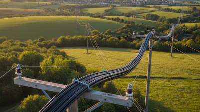
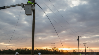
An aerial fibre cable carries high-speed data above ground, usually along utility poles, bridges, or dedicated support structures. Unlike buried fibre, it remains visible to technicians and exposed to wind, rain, ice, sunlight, and falling branches. That exposure makes its design important.

Gary Bolton, president and CEO of the Fiber Broadband Association, has stated, “Fiber is the only technology that can support all of the applications we can imagine today and in the future.” His observation explains the cable’s growing value, but it does not tell the whole story. The installation environment matters greatly.

An aerial fibre cable may use a messenger wire for support, or it may be self-supporting, as with all-dielectric self-supporting cable. Technicians attach the cable carefully between poles, allowing controlled sag without creating excessive tension. Inside, glass fibres transmit information as pulses of light. The cable itself does not amplify data. Optical equipment at each end sends, receives, and manages those signals.

In practice, small details can decide reliability. A loose closure may admit moisture. Excessive tension may damage fibres. A clearance that looks acceptable today may become unsafe after heavy snow or strong wind.

That is the practical weakness.

Aerial networks are often faster to deploy and easier to inspect. However, they demand regular checks, accurate pole surveys, and disciplined maintenance. This guide examines how aerial fibre cable works, where it performs well, and why installation quality can matter as much as the fibre inside.
What Is Aerial Fibre Cable and How Does It Work?

Definition and Core Components of Aerial Fibre Cable

What Is Aerial Fibre Cable and How Does It Work?

Definition and Core Components of Aerial Fibre Cable

Aerial fibre cable is an outdoor optical cable installed between poles, towers, or building supports. It carries data as rapid light pulses through thin glass fibres. OECD Broadband Statistics for December 2023 reported that fibre represented about 42% of fixed broadband subscriptions across OECD economies. That growth increases demand for reliable overhead networks.

The optical fibre is the working core, while buffer tubes protect it from moisture and bending. Strength members, often made from non-metallic material, resist pulling forces during installation. A water-blocking layer limits moisture movement. The outer jacket protects against sunlight, rain, ice, and abrasion. Some designs include a messenger wire or integrated support element. Hardware such as suspension clamps and dead-end fittings keeps the cable safely positioned.

During operation, optical transmitters convert electrical signals into light. Receivers change those pulses back into usable data. ITU-T G.652.D defines key characteristics for widely used single-mode fibre, including low-loss transmission across common wavelength ranges. In practice, installation quality matters as much as the fibre specification. Excessive tension, sharp bends, or incorrect sag can increase signal loss. The cable may look simple from the ground. It is not. Wind loading and temperature changes constantly affect its mechanical condition, and field measurements sometimes reveal assumptions that design drawings missed.

How Aerial Fibre Cables Transmit Data Through Optical Signals

What Is Aerial Fibre Cable and How Does It Work?

Aerial fibre cable carries internet, voice, and video data above the ground. It hangs between poles or towers, often across streets and rural areas. Inside, thin glass fibres guide light pulses over long distances. A transmitter converts electrical data into rapid optical signals. The light travels through the fibre core, while the cladding keeps it contained. At the receiving end, a photodiode changes the light back into electrical data. No electrical current travels through the glass.

The process is fast, but not perfect. Light weakens over distance because of bending, dirty connectors, and tiny imperfections. Field technicians measure this loss with an optical time-domain reflectometer. A sudden spike can reveal a damaged section or poor splice. Aerial installation also needs correct tension and safe clearance from trees, vehicles, and power lines. The explanation sounds clean. Real networks are less tidy.

Tips: Keep the cable’s bend radius within the manufacturer’s specification. Avoid sharp ties that crush the outer jacket. Inspect connectors before testing, even when they look clean. Check pole movement after strong wind or ice. Small alignment errors can reduce signal quality. Records matter too; label every splice and inspection point. Fault finding becomes harder when installation notes are incomplete.

What Is Aerial Fibre Cable and How Does It Work? - How Aerial Fibre Cables Transmit Data Through Optical Signals

Data Dimension Typical Data or Specification How It Relates to Aerial Fibre Cable Operation
Cable Definition Outdoor optical-fibre cable installed above ground The cable is supported on poles, towers, or messenger wires rather than buried directly underground. Its design must withstand wind, rain, sunlight, ice, and mechanical loading.
Transmission Medium Glass optical fibre Data travels through a glass core as pulses of light. The surrounding cladding has a lower refractive index, allowing the light to remain inside the core through total internal reflection.
Common Fibre Type Single-mode fibre; approximately 8–10 µm core diameter Single-mode fibre is widely used for aerial telecommunications because it provides low signal loss and supports long-distance, high-capacity links.
Typical Operating Wavelengths 1,310 nm, 1,490 nm, 1,550 nm, and 1,625 nm Optical transmitters and receivers use specific wavelength bands. The 1,550 nm region generally offers low fibre attenuation and is commonly used for long-distance transmission.
Signal Conversion Electrical data → optical pulses → electrical data A transmitter converts digital electrical signals into modulated light from a laser or light-emitting device. At the receiving end, a photodetector converts the light back into electrical data.
Common Attenuation Range About 0.20–0.40 dB/km for standard single-mode fibre Attenuation represents optical power lost as the signal travels. Lower attenuation allows longer spans between active equipment, although connectors, splices, bends, and environmental conditions also contribute to link loss.
Data Capacity From 1 Gb/s to 100 Gb/s or more per optical channel The cable itself does not determine one fixed data rate. Capacity depends on the fibre count, optical transceivers, modulation method, wavelength technology, and network equipment.
Cable Construction Fibre units, buffer tubes, strength members, water-blocking elements, and an outer jacket These layers protect the fibres from tensile force, crushing, moisture, temperature changes, and vibration while maintaining the bend performance required for installation.
Self-Supporting Design All-dielectric self-supporting cable or messenger-supported cable Self-supporting designs use non-metallic strength members and do not require a separate support wire. Other designs are lashed or attached to a messenger wire that carries the mechanical load.
Typical Cable Diameter Approximately 8–20 mm, depending on fibre count and construction A higher fibre count and stronger mechanical design generally increase the cable diameter. The exact dimension must be selected according to span length, loading, and installation conditions.
Typical Fibre Count Common configurations range from 12 to more than 288 fibres The required fibre count depends on the number of subscribers, network routes, spare capacity, and whether the cable is used for access, distribution, or backbone service.
Pole Span Often about 50–200 m; engineering-dependent The permitted span is determined by cable construction, sag, wind pressure, ice loading, pole strength, clearance requirements, and local installation regulations.
Environmental Protection UV-resistant jacket and sealed or water-blocked internal structure The outer sheath helps resist ultraviolet radiation and weathering, while water-blocking materials limit the movement of moisture along the cable if the jacket is damaged.
Mechanical Load Designed for installation tension, wind, ice, and its own weight During installation, pulling tension must remain within the cable's rated limit. After installation, sag and support hardware must be controlled to maintain safe ground and utility clearances.
Bending Requirement Minimum bend radius commonly specified as a multiple of cable diameter Excessive bending can increase optical loss or permanently damage the fibre. Installers follow separate bend-radius limits for conditions with and without applied tensile load.
Key Advantages Rapid deployment, high bandwidth, low electromagnetic interference Aerial installation can reduce excavation work and simplify route expansion. Fibre is immune to electromagnetic interference because it carries light rather than electrical current.
Main Limitations Exposure to weather, vehicle impact, falling objects, and support-structure failures Regular inspection may be required to identify excessive sag, jacket damage, damaged hardware, vegetation contact, or clearance problems.
Basic Transmission Sequence Encode → modulate light → guide through fibre → detect → decode Network equipment encodes data, changes the intensity or other properties of an optical carrier, sends it through the fibre, and reconstructs the original digital information at the destination.

Note: Values shown are common engineering ranges or representative specifications. Actual aerial cable dimensions, span limits, attenuation, fibre count, and environmental ratings vary according to the cable design, route conditions, installation method, and applicable standards.

Types of Aerial Fibre Cable and Their Supporting Structures

Aerial fibre cable carries data through glass strands installed above streets, usually on poles. Light pulses travel inside the core, while the cladding keeps the signal confined. Unlike buried fibre, aerial cable allows faster deployment and easier visual inspection. However, wind, ice, sunlight, and falling branches can expose weaknesses.

The main cable types include loose-tube, ribbon, and figure-eight self-supporting designs. Loose-tube cable protects fibres inside gel-filled tubes and suits long outdoor routes. Ribbon cable stacks fibres closely, helping technicians complete high-count splices quickly. Figure-eight cable uses an integrated messenger wire, reducing the need for separate support hardware.

The FTTH Council Europe Market Panorama 2024 reported more than 250 million homes passed by fibre in Europe, increasing pressure for dense, efficiently supported networks.

Supporting structures determine reliability. Wooden poles remain common for rural distribution because they are practical and adaptable. Concrete and steel poles handle heavier loads or harsh environments, but they can increase installation costs. ADSS cable needs no metallic messenger and is attached with suspension and anchoring fittings. Lashings can secure conventional optical cable to an existing messenger. Engineers must calculate span length, sag, tension, ice, and wind loading under local utility rules. The National Electrical Safety Code provides clearance guidance, but local requirements still vary. Field experience shows that drawings alone miss tree movement and pole deflection. A perfect design is unlikely. Periodic inspection remains essential.

Installation, Protection, and Maintenance of Aerial Fibre Networks

What Is Aerial Fibre Cable and How Does It Work?

Aerial fibre cable carries light-based data between poles, buildings, and access points. It uses a supporting messenger, or a self-supporting structure, to resist tension. The OECD Broadband Statistics report states that fibre represented about 42% of fixed broadband subscriptions across OECD countries in December 2023. That growth increases pressure on outdoor networks.

Installation starts with a route survey, pole inspection, and accurate span measurements. Crews must check wind exposure, tree movement, road clearance, and existing utilities. Local electrical and safety codes always control final clearances. There is no universal safe height. Cable tension must also match the manufacturer’s limits. Excessive tension can damage the cable, while loose spans may sag dangerously. Keep slack visible. Label it clearly.

Protection depends on details that are easy to overlook. Use sealed closures, drip loops, abrasion guards, and bend-radius controls near poles. The ITU Facts and Figures 2024 report estimates that 5.5 billion people used the Internet in 2024, making service interruptions more costly for communities. Maintenance teams should inspect cables after storms, record optical loss, and test closures for moisture. They should also remove climbing vegetation before it loads the span. No inspection plan is perfect. Undocumented repairs still create blind spots, and field records are often incomplete. A practical network improves when crews question old assumptions, not when they simply repeat them.

What Is Aerial Fibre Cable and How Does It Work?

Aerial fibre cable is installed on poles or other overhead supports. Its optical fibres transmit data through pulses of light, while the outer jacket, strength members, suspension hardware, and regular inspections protect the cable from wind, ice, temperature changes, and mechanical stress.

The chart shows typical maximum attenuation reference values for standard single-mode fibre at common operating wavelengths. Lower attenuation means less optical signal loss over distance. During maintenance, technicians use optical time-domain reflectometers and power meters to check whether ageing, bending, water ingress, or installation damage has increased signal loss.

Advantages, Limitations, and Common Applications of Aerial Fibre Cable

Aerial fibre cable is installed above ground on poles, towers, or building structures. Inside, glass fibres carry data as pulses of light. A protective sheath surrounds the fibres, while a messenger wire supports the cable between attachment points.

Its main advantage is speed. Crews can often deploy a route without opening roads or disturbing buried utilities. This reduces civil work and may lower installation costs. Repairs can also be easier because technicians can inspect visible spans. Rural broadband, mobile network backhaul, campus connections, and temporary event networks commonly use aerial fibre. The fibre itself does not conduct electricity, but nearby power infrastructure still requires careful clearance planning.

The limitations are practical and sometimes underestimated. Strong wind can create cable movement, while ice adds weight to each span. Falling branches, vehicle strikes, ultraviolet exposure, and poor vegetation control may cause damage. Regular inspections matter. Technicians should check sag, attachment hardware, clearances, and pole conditions. Good tension calculations are essential near corners and long crossings. Aerial routes are also more visible, which can affect local appearance and physical security.

In my experience, installation plans often look tidy on paper but change after a site survey. One overlooked tree can become a recurring fault. Weather data, access requirements, and maintenance responsibility should be confirmed before construction. Even small oversights matter.