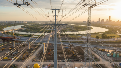
In 2026, telecom cables remain the physical foundation of digital connectivity. Fiber carries most long-distance traffic, while coaxial and hybrid fiber-coaxial systems still support many access networks. Submarine cables connect continents through carefully engineered routes beneath busy oceans.
The International Telecommunication Union reported that 5.5 billion people were online in 2024. That figure increases pressure on networks, especially around ports, data centers, and fast-growing cities. TeleGeography’s submarine cable research also shows a continuing expansion of international capacity and new cable investment. The message is clear: cable selection is no longer a simple purchasing decision.
“The internet is not in the cloud. It’s in the ocean,” explains Nicole Starosielski, author of The Undersea Network. Her statement makes the hidden infrastructure easier to picture: glass fibers inside a protected cable, landing stations near shore, and repair vessels waiting offshore.
This guide examines the top types of telecom cables for global buyers in 2026. It compares single-mode fiber, ribbon fiber, armored fiber, ADSS aerial cable, coaxial cable, hybrid fiber-coaxial cable, and submarine cable systems. Each option serves a different environment. A city backbone needs low-loss fiber. A rural overhead route may need strong, lightweight ADSS construction. A subsea link demands advanced armor and strict testing.
Standards matter. So do installation skills, supplier traceability, attenuation results, bend performance, and warranty terms. Buyers should review ITU-T recommendations, IEC testing practices, and regional compliance requirements before ordering.
Price alone can mislead. Sometimes, badly. A cheaper cable may create higher maintenance costs later. Even this framework has limits, because local labor, terrain, climate, and network architecture can change the best choice.
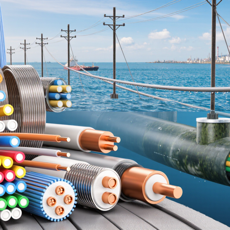
Single-mode fiber forms the backbone of modern telecom networks from 100G to 800G. Its tiny core carries signals over long distances with low attenuation and limited dispersion. Global buyers often select OS2 fiber for data centers, metro links, and international routes. At 100G, it provides stable capacity across demanding connections. Higher rates require stricter control of loss, reflection, and connector quality. 800G exposes weak points quickly.
Installation details matter as much as cable specifications. Technicians should confirm the correct fiber class, bend radius, jacket rating, and connector polish. A clean end face matters. Dust can create unexpected insertion loss. During acceptance testing, power meters and OTDR equipment can reveal faults that visual checks miss. I have seen a short, sharply bent section reduce performance after a careful installation. The drawing looked perfect. The cable route was not.
Procurement teams should request test reports, traceable measurements, and clear tolerance data. They should also check compatibility with transceivers, patch panels, and future network upgrades. Standardized components simplify maintenance across different regions. However, low purchase cost can hide higher testing and repair expenses. I have learned that planning for spare cable and documented fiber paths prevents avoidable delays. No design is perfect. Field conditions change, technicians make mistakes, and network demand grows faster than forecasts. Single-mode fiber remains dependable when engineering discipline continues beyond the purchase order.
Multimode fiber supports practical 10–100G links across data centers and campus systems. Its short-reach design suits server rows, building risers, and equipment rooms. OM3 and OM4 fiber commonly serve 10G connections, while selected parallel-optic systems support 40G and 100G transmission. Distance, connector count, and transceiver type must be checked together. A 100G link is not simply a faster 10G cable.
In data centers, short fiber trunks reduce pathway congestion and simplify airflow planning. High-density connectors can save rack space, but they demand accurate polarity control. Technicians should label each lane clearly. Small mistakes become expensive during maintenance. Clean end faces are equally important. Dust can increase insertion loss and create unstable links. Testing with suitable optical loss equipment provides stronger evidence than visual inspection alone.
Campus networks often include longer pathways, uneven temperatures, and crowded conduits. Engineers should confirm the actual route length before selecting multimode fiber. A link that works in a laboratory may fail after extra patch panels are added. I have seen designs focus heavily on bandwidth while overlooking bend radius and future moves. That approach needs reconsideration. Buyers should request insertion-loss budgets, test records, fiber grades, and support documentation. A carefully measured 40G path may be more dependable than an optimistic 100G design.
Cat 8 copper cable targets high-density short links, not every office outlet. Under IEEE 802.3bq, it supports 25GBASE-T and 40GBASE-T over channels up to 30 meters. ANSI/TIA-568.2-D specifies performance to 2,000 MHz. That bandwidth helps connect servers, switches, and storage racks with low latency. The distance is strict, however. A crowded pathway, poor termination, or excessive patching can reduce practical performance.
The Ethernet Alliance’s 2024 Ethernet Roadmap shows continuing demand for higher-speed links in data centers and enterprise networks. This supports Cat 8 for compact rack layouts, where fiber may be unnecessary or harder to deploy. In my field experience, installation quality matters more than the printed speed. Shield continuity, bend radius, grounding, and compatible connectors must be checked. A 40Gbps rating is not a promise for every existing system. It is a design target.
Tips: Measure the complete channel first. Keep it below 30 meters. Use tested Cat 8 components together. Certify each link with a calibrated field tester, including insertion loss and crosstalk. Do not mix unverified hardware. I would not specify Cat 8 automatically; Cat 6A may offer better value for many 10Gbps links. That judgment can change as traffic grows, which deserves review.
2026 Top Types of Telecom Cables for Global Buyers
Coaxial cable remains important as DOCSIS 4.0 networks expand. Under suitable conditions, DOCSIS 4.0 can support downstream speeds up to 10Gbps. The cable is not the only factor. Network design, spectrum allocation, signal distance, and equipment capability also affect performance.
A field technician should inspect shielding before installation. Weak shielding can allow interference from nearby power equipment. Moisture is another quiet problem. Water entering damaged jackets may raise attenuation and create unstable service. Choose cables with durable outer jackets for outdoor routes and demanding climates. Connector quality matters too. Poor compression can cause reflections and signal loss.
Short runs are usually easier to manage. Long routes require careful testing. Technicians should measure insertion loss, return loss, and ingress after installation. Temperature changes can also affect cable behavior, especially on exposed lines. In my experience, product sheets often look more convincing than real sites. That is worth remembering.
A 10Gbps claim should therefore be treated as a network target, not a guaranteed result. Buyers should request test data, construction details, and compatibility information before approving large shipments. Some projects may need upgraded splitters, amplifiers, or distribution equipment. The cable alone cannot repair an outdated network.
Submarine fiber-optic cables carry enormous data volumes between continents, often reaching multi-terabit capacity through advanced wavelength multiplexing. They support cloud services, financial networks, video platforms, and international business traffic. A single cable system may cross thousands of kilometers beneath busy ocean routes. Inside, hair-thin glass fibers transmit pulses of light with remarkably low delay.
Reliable performance depends on more than fiber capacity. Network planners examine route length, seabed conditions, landing-station resilience, repeater spacing, and protection from fishing activity or anchoring. Armored sections may be selected near shore, where risks are higher. Deep-water sections usually require different construction decisions. A neat route map can mislead. Weather, repair access, and political conditions still deserve careful review.
Tips: Compare total system capacity with realistic peak demand, not advertised capacity alone. Ask for test records, optical budgets, repair procedures, and clear maintenance responsibilities. Check whether diverse routes exist before choosing a single connection. Small details matter.
Multi-terabit design also requires strong terrestrial links after the cable reaches land. A powerful subsea system cannot solve congestion inside a data center or landing network. Buyers should review latency targets, upgrade options, service-level commitments, and spare-parts planning. Technical specifications may look perfect, yet future traffic growth can expose weak assumptions. Conservative forecasting is safer, although it may increase initial costs. Repairs are never instant. Clear documentation and experienced installation teams can reduce uncertainty across the cable’s operating life.