2026 Best Cable Duct Installation Guide for Global Buyers
Choosing the right cable duct installation method can protect network performance, shorten maintenance time, and prevent costly site failures. For global buyers, the decision involves more than duct size or unit price. Climate, soil movement, traffic loads, cable heat, water exposure, and local construction requirements all matter.
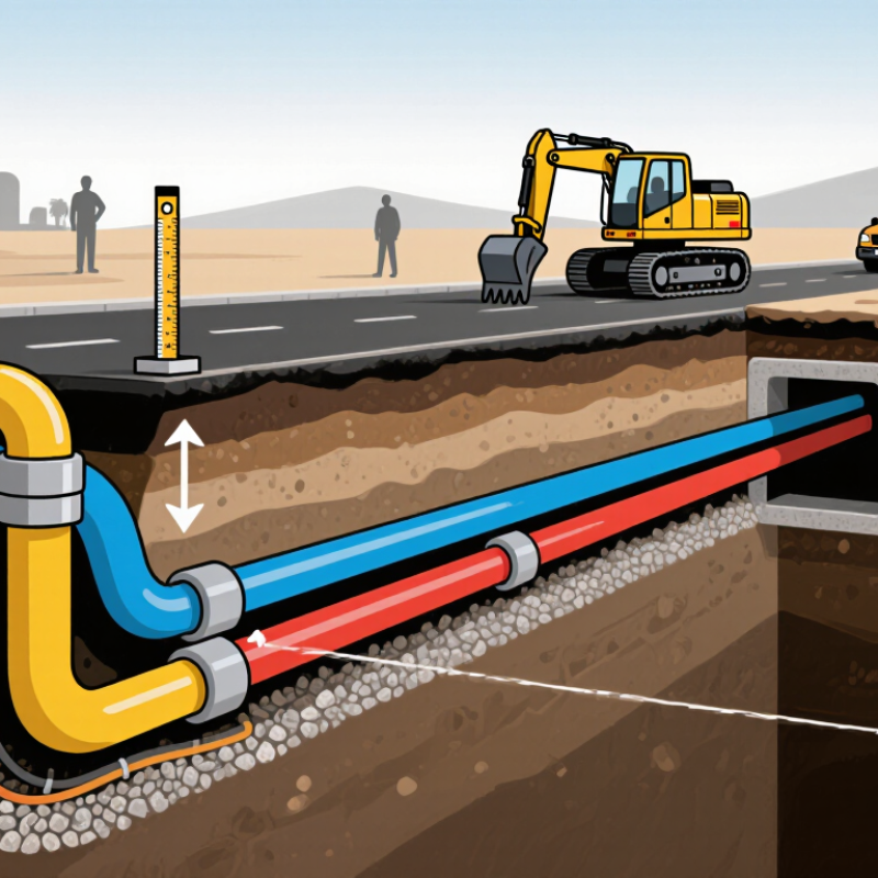
Cable-management engineer Martin Keller offers a practical reminder: “A duct is successful only when it protects today’s cables and leaves room for tomorrow’s work.” This principle shapes the guidance in this article. It covers route planning, trench preparation, duct materials, joint sealing, bend radius, cable pulling, inspection, and backfilling. Clear photographs, measured depths, and controlled pulling tension are not optional details. They are evidence of competent work.
Small mistakes become expensive underground. A sharp bend can damage insulation. Poorly sealed joints can collect water. Excessive filling can restrict airflow and complicate future repairs. Yet real projects rarely follow perfect drawings. Unexpected rock, crowded corridors, and incomplete site records may force careful changes. That is where professional judgment matters.
This 2026 guide is written for contractors, engineers, distributors, and procurement teams comparing solutions across regions. It encourages buyers to request load data, material specifications, installation tolerances, testing records, and warranty terms. Local standards still require verification. A product suitable for a dry indoor plant may fail beside a coastal road.
Good cable duct installation is not merely placing plastic or concrete underground. It is building an accessible, documented, and resilient cable pathway. The process needs discipline. It also needs honest review when the original plan proves incomplete.
Cable Duct Types, Materials, and IEC 61084-2-1 Compliance
Selecting a cable duct starts with the installation environment, not appearance. Wall-mounted trunking suits offices, workshops, and equipment rooms. Floor ducts protect routes beneath raised floors. Flexible ducts help around moving panels, but they need careful support. Separate power and data pathways where interference or maintenance access matters.
Material choice affects service life. PVC is lightweight, corrosion-resistant, and easy to cut. Galvanized steel offers stronger impact resistance and better protection in demanding areas. Aluminum reduces weight and resists corrosion, but its joints require attention. Check temperature, moisture, UV exposure, chemical contact, and fire performance before ordering. A duct that looks robust may still deform near heat sources.
IEC 61084-2-1 covers particular requirements for cable trunking systems mounted on walls and ceilings. Buyers should request evidence of relevant testing, product classification, dimensions, loading data, and installation instructions. Verify cover retention, mechanical strength, continuity provisions, and resistance to flame propagation where applicable. The standard does not replace local wiring rules or project specifications. Confirm the current edition and any national deviations.
On site, measure the real cable fill, bend radius, and future capacity. Leave usable space for maintenance. Overfilled ducts create heat and make fault finding unpleasant. I have seen neat installations fail because the cover was forced closed. That mistake is easy to repeat. A short sample installation can reveal weak clips, sharp edges, or poor corner alignment before a full shipment arrives.
Measure Cable Loads and Maintain the 40% Recommended Fill Capacity
2026 Best Cable Duct Installation Guide for Global Buyers
Accurate cable-load measurement protects performance, safety, and future maintenance. Measure every cable’s outside diameter, including insulation and protective layers. Then calculate the total cross-sectional area, not only the cable count. A duct carrying twelve thin cables may need less space than one carrying four heavy power cables.
Keep the installed cable area below 40% of the duct’s usable internal area. This allowance supports airflow, pulling tension, and future additions. It also reduces pressure on insulation during installation. Separate power, control, and communication cables when required by the project design. Check bend radius at corners, joints, and entry points. A duct can meet the fill limit and still fail because cables bend too sharply. I have seen clean layouts become difficult during maintenance because the original measurements ignored connectors and spare capacity.
Tips:
Measure twice. Record actual diameters. Include a 20% expansion allowance where future circuits are likely. Use a flexible measuring tape around irregular bundles, then verify the result with a calculation sheet. Leave access space near inspection covers. Do not rely on visual estimates. They often look convincing, but they are not precise. Review the plan with the installer before cutting the duct. Small site changes can alter the fill ratio, and that detail is easy to miss.
Plan Routes Using Minimum Bend Radii and Required Access Points
Before ordering cable duct, draw the route at installation scale. Mark every wall, riser, machine entry, and future branch. Then compare each turn with the cable’s specified minimum bend radius. Do not estimate it by eye. A tight corner can damage insulation, increase pulling force, and delay commissioning.
Use long-radius elbows or gradual offsets where space allows. For several bends in one run, provide an access point before pulling cables. Keep access points reachable, dry, and clear of moving equipment. A practical rule is simple: pull sections should not become blind tunnels. Their spacing should reflect cable size, duct dimensions, bend count, and local requirements. Check covers, fasteners, and drainage details on the actual site. Drawings can miss a low beam or a blocked service corridor.
Allow spare capacity, but do not treat empty space as unlimited flexibility. Separate power and communication routes when project requirements demand it. Use supports that prevent sagging between access points. At each entry, protect cables from sharp edges and uncontrolled friction. For international projects, confirm dimensions, fire performance, material ratings, and installation rules locally. Requirements vary. Record radius calculations, route changes, and inspection photos for reliable handover. A route may look perfect on paper and still need revision after a site walk. That is not failure; it is useful evidence.
Install Ducts with IP Ratings from IP40 to IP68 for Site Conditions
2026 Best Cable Duct Installation Guide for Global Buyers
Choosing the correct IP rating starts with the actual site conditions. IP40 protects against solid objects above one millimeter, but offers no water protection. Use it only in clean, dry indoor areas. IP54 suits locations with limited dust and light splashing. It may fail where cleaning involves strong water pressure.
For exposed installations, IP65 provides dust-tight protection and resistance to water jets. IP66 handles stronger water jets, making it suitable for washdown zones and outdoor equipment. IP67 supports temporary immersion, usually up to one meter under specified test conditions. IP68 allows deeper or longer immersion, but the manufacturer must define the tested depth and duration.
Seal the cable entries carefully. The duct rating can be excellent, yet an open gland can destroy the complete protection level. Check bends, joints, drainage paths, and cover pressure before energizing equipment. Field inspections often find small gaps near corners. They are easy to miss. Dust can enter through unused openings, while trapped water may freeze and split a joint. Select compatible seals for temperature, chemicals, sunlight, and cable movement. Do not assume IP68 is always better; it can add cost and complicate maintenance. Installation records should include the selected rating, site exposure, inspection date, and any limitations. Recheck the system after the first heavy rain or cleaning cycle.