
2026 Best Fibre Optic Network Solutions for Global Buyers
Choosing a fibre optic network in 2026 requires more than comparing advertised speeds. Global buyers must examine performance, compatibility, support, and long-term operating costs. A reliable solution should match the site’s distance, bandwidth demand, climate, and expansion plans. It should also include documented testing, clear warranty terms, and traceable component specifications.
This guide explores network solutions for data centres, telecommunications providers, industrial facilities, campuses, and international projects. It considers single-mode and multimode fibre, fibre counts, connector types, optical transceivers, passive infrastructure, and management systems. Practical experience matters here. A cable may meet a headline specification yet fail when installation conditions are poor or maintenance access is limited.
Small details matter.
Buyers should review insertion loss, return loss, bend performance, fire ratings, and environmental protection. They should also confirm compliance with relevant regional standards and procurement requirements. Vendor reputation is important, but independent test reports and deployment references provide stronger evidence. Local technical support can prevent a minor connector issue from becoming a costly outage.
No solution fits every market. A premium design may be unnecessary for a short campus link, while a low-cost option may create serious risks during future upgrades. This overview therefore compares technical value, resilience, installation practicality, and lifecycle support. Some recommendations may remain open to debate, because network conditions differ widely. Careful planning, professional testing, and honest risk assessment will help global buyers build faster, safer, and more adaptable fibre infrastructure.
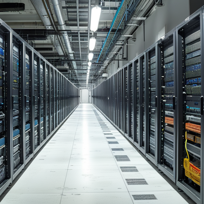
Global Fibre Optic Network Solutions: Definition, Scope, and Core Components
Global fibre optic network solutions are integrated systems that move data through glass fibres across cities, countries, and continents. Their scope includes access networks, metropolitan links, data centres, submarine cables, monitoring systems, and maintenance services. Fibre supports high capacity, low latency, and stronger signal performance over long distances.
The OECD’s broadband statistics showed fibre exceeded 40% of fixed broadband subscriptions across member economies in 2023. The ITU Global Connectivity Report 2022 also estimated that 2.7 billion people remained offline, showing that coverage gaps still shape network planning. TeleGeography’s 2024 Global Bandwidth Research Service reported continued rapid growth in international bandwidth demand. These figures make fibre expansion necessary, but expansion alone is not enough.
Core components include optical fibre cables, transceivers, splice closures, patch panels, optical line terminals, routers, power systems, and network management software. A practical design also needs diverse routes, protected ducts, accurate loss testing, and spare capacity. Details matter. In field projects, poor joint sealing or incorrect bend control can reduce reliability long before fibre capacity is exhausted. That assumption needs testing. Climate, terrain, local permits, repair access, and electricity stability can change the best solution for each market. A technically impressive network may still fail commercially if installation skills and replacement parts are unavailable.
2026 Best Fibre Optic Network Solutions for Global Buyers - Global Fibre Optic Network Solutions: Definition, Scope, and Core Components
| Solution Type | Definition and Primary Role | Typical Downstream / Upstream Capacity | Typical Fibre Architecture | Reach and Split Characteristics | Relevant Technical Standards | Best-Fit Applications | Main Advantages | Key Limitations | 2026 Deployment Status |
|---|---|---|---|---|---|---|---|---|---|
| GPON Fibre Access | A passive optical access system that connects a central optical line terminal to multiple subscribers through passive splitters. | Up to 2.488 Gbit/s downstream and 1.244 Gbit/s upstream at the physical layer. | Point-to-multipoint; typically uses single-mode fibre with passive optical splitters. | Common physical reach is up to 20 km, with optical split ratios commonly ranging from 1:32 to 1:64 depending on the optical budget and network design. | ITU-T G.984 series. | Residential broadband, basic small-business access, rural fibre deployment and cost-sensitive markets. | Broad ecosystem, low outside-plant power consumption, mature equipment and efficient shared-fibre construction. | Lower upstream capacity and less long-term headroom than newer symmetric or higher-speed PON systems. | Mature and widely deployed |
| XGS-PON Fibre Access | A symmetric passive optical network designed to provide high-speed access for residential, enterprise and multi-service networks. | Up to 10 Gbit/s downstream and 10 Gbit/s upstream at the physical layer. | Point-to-multipoint; supports shared passive optical distribution networks and coexistence with selected legacy PON systems. | Common physical reach is up to 20 km; split ratios of 1:32 or 1:64 are frequently used, subject to optical budget and service requirements. | ITU-T G.9807.1. | Multi-gigabit broadband, business connectivity, mobile transport, campus networks and high-density housing. | Symmetric capacity, strong upgrade path, efficient fibre sharing and suitability for demanding upload services. | Requires higher optical and electronic investment than GPON; shared bandwidth still needs capacity planning. | Mainstream growth solution |
| 25G-PON Access | A next-generation passive optical access approach that increases capacity on the optical access layer for advanced broadband and enterprise services. | Common implementations target approximately 25 Gbit/s downstream, with upstream options depending on the selected standard and equipment profile. | Point-to-multipoint over single-mode fibre; may be introduced as an overlay or evolution alongside existing PON technologies. | Reach and split ratio depend on the optical budget, wavelength plan and deployment profile; access designs commonly target kilometre-scale reach up to approximately 20 km. | IEEE 802.3ca for 25G-EPON; other 25G PON profiles may use different industry specifications. | High-capacity residential access, enterprise access, mobile xHaul, data-intensive campuses and future-proof metropolitan access. | Higher per-PON capacity and improved support for demanding users, mobile networks and wholesale access. | Ecosystem maturity, interoperability and migration requirements must be evaluated carefully before large-scale deployment. | Emerging and selective |
| Active Ethernet Fibre | A dedicated or switched fibre connection in which active Ethernet equipment directs traffic between access nodes and customers. | Common access speeds range from 1 Gbit/s to 10 Gbit/s, with higher rates available through suitable optical modules and switching equipment. | Point-to-point or switched point-to-multipoint; generally uses dedicated fibre strands per subscriber or logical service. | Reach is determined by Ethernet optics and network architecture; 10 km and 40 km optical classes are common in access and metropolitan environments. | IEEE 802.3 Ethernet standards and applicable optical-interface specifications. | Enterprise connectivity, leased lines, campuses, industrial sites, government networks and applications requiring dedicated bandwidth. | Predictable bandwidth, straightforward service separation, flexible traffic management and strong enterprise compatibility. | More active field equipment, higher power and maintenance requirements, and potentially higher fibre-count needs. | Established specialist solution |
| Metro Ethernet over Fibre | A carrier-grade Ethernet transport service used to connect sites, aggregation points, data centres and access networks across metropolitan areas. | Typically supports 1, 10, 25, 100 or 400 Gbit/s links, depending on the optical interface, distance and transport design. | Point-to-point, ring, mesh or protected multipoint architecture over single-mode fibre. | Metro reach commonly spans several kilometres to tens of kilometres; protection and latency depend on the physical route and switching design. | IEEE 802.3 Ethernet standards; MEF service definitions may be used for carrier Ethernet service attributes. | Business WAN, mobile backhaul, data-centre interconnection, public-sector networks and regional aggregation. | Scalable bandwidth, service-level control, flexible topology and compatibility with packet-based transport. | Requires robust operations, synchronisation, protection and traffic-engineering practices. | Widely established |
| Fibre-to-the-Home / Fibre-to-the-Premises | A deployment model that extends optical fibre directly to a residence, business premises or multi-dwelling building. | Capacity depends on the access technology; modern deployments commonly support multi-gigabit service tiers. | Usually uses PON, but active Ethernet and other architectures are also possible. | Distribution reach is normally designed for access-network distances up to approximately 20 km, including permitted splitter and connector losses. | May use ITU-T PON standards, IEEE Ethernet standards, local construction codes and national optical safety regulations. | Residential broadband, smart buildings, telehealth, remote work, education and small-business services. | High capacity, low latency, long service life and strong resistance to electromagnetic interference. | Civil works, rights-of-way, indoor access, building entry and customer installation can represent a major portion of total project cost. | Global strategic access model |
| Fibre-to-the-Building / Fibre-to-the-Cabinet | A hybrid access model that brings fibre close to users and uses copper or another short-reach medium for the final segment. | Fibre backhaul may support multi-gigabit capacity; final-user speed depends strongly on copper length, condition and access technology. | Fibre to a building, street cabinet or distribution point, followed by a short non-fibre drop. | Fibre reach can be long, but the final copper segment is typically limited to short distances to preserve performance. | May combine fibre transport standards with DSL, Ethernet or building-distribution standards. | Brownfield upgrades, dense urban areas, multi-dwelling buildings and locations where full fibre construction is delayed. | Reduces immediate civil works and can accelerate coverage where existing ducts or copper are reusable. | Lower and less consistent end-user performance than fibre-to-the-premises; copper maintenance remains necessary. | Transitional and brownfield |
| Data-Centre Interconnect Fibre | A high-capacity optical connection between data centres, cloud facilities, internet exchanges or regional compute sites. | Common link rates include 100, 400 and 800 Gbit/s, with capacity determined by transceiver technology, lane count and optical reach. | Usually point-to-point single-mode fibre with diverse paths, optical line systems or coherent transmission for longer distances. | Short-reach interconnects may cover a few kilometres; metro and regional systems can extend from tens to several hundred kilometres with appropriate optics. | IEEE 802.3, optical-interface multi-source agreements and applicable coherent optical specifications. | Cloud infrastructure, disaster recovery, storage replication, content delivery and high-volume inter-site traffic. | Very high capacity, low latency, scalable architecture and strong support for data-intensive workloads. | High availability requires route diversity, precise optical engineering, monitoring and careful power and cooling planning. | High-priority growth area |
| Fibre-Optic Mobile Transport | A fibre-based transport network connecting radio sites, distributed units, aggregation nodes and core-network locations. | Capacity varies by radio architecture; links commonly range from 10 Gbit/s to 100 Gbit/s or more in high-density deployments. | Point-to-point, ring or routed aggregation using single-mode fibre with synchronisation support. | Reach varies from short access links to metropolitan and regional spans; latency, timing and protection are critical design factors. | Ethernet and optical transport standards with mobile synchronisation requirements such as SyncE and IEEE 1588 Precision Time Protocol. | 4G and 5G backhaul, fronthaul, midhaul, small-cell aggregation and private mobile networks. | Supports high traffic growth, low latency, network slicing requirements and reliable site aggregation. | Traffic patterns, timing accuracy, fibre availability and protection requirements can make planning complex. | Expanding with mobile densification |
| Submarine Fibre Cable Systems | Long-distance undersea optical infrastructure used to connect countries, continents, islands and international data hubs. | System capacity is engineered using multiple fibre pairs and wavelength channels; total design capacity can reach many terabits per second. | Armoured or unarmoured submarine cable, repeaters for long wet segments, branching units and shore-based terminal equipment. | Designed for hundreds to thousands of kilometres; route engineering must address seabed conditions, power feeding, repair access and landing-station diversity. | International marine, optical transmission, environmental and telecommunications requirements; specifications vary by project. | International internet connectivity, cloud regions, intercontinental enterprise networks and island connectivity. | Extremely high aggregate capacity, long-distance reach and strategic route diversity. | Very high capital cost, lengthy permitting, complex marine installation and exposure to cable cuts or geopolitical disruption. | Strategic global infrastructure |
| Fibre Monitoring and Management Layer | A diagnostic and operational layer that measures fibre condition, identifies faults and supports preventive maintenance. | Monitoring capacity is measured by ports, fibres, test frequency and alarm coverage rather than by subscriber throughput. | Optical time-domain reflectometry, optical power monitoring, remote test units, patching systems and network-management software. | Detection distance depends on test equipment, splitters, connectors, fibre loss and the selected measurement method. | ITU-T recommendations and applicable IEC test, measurement and fibre-performance practices. | Carrier networks, data centres, submarine landing sites, utility networks, railways and critical infrastructure. | Faster fault isolation, improved service assurance, lower mean time to repair and better asset visibility. | Requires calibrated test procedures, accurate fibre records, skilled personnel and integration with operational systems. | Recommended for critical networks |
Note: Capacity, reach and split figures are engineering reference values. Actual performance depends on optical budget, fibre quality, connector and splice loss, transceiver class, route design, environmental conditions, regulatory requirements and network traffic policies.
Related Posts
-
10 Best Telecom Fibre Suppliers for Global Buyers
-

How to Choose the Right Fibre Optic Infrastructure?
-

What is Fibre Drop Cable and Its Uses in Network Installation
-
Top Tips for Choosing the Right FO Cable for Your Needs?
-
What is Fibre Cable and How Does It Work for Your Connectivity Needs
-
10 Essential Tips for Installing Fibre Optic Ducting Like a Pro